Understanding Mechanism Design
The Base panel allows you to sketch kinematic diagrams of planar mechanisms containing links and revolute and prismatic joints. These mechanisms can be one- or multi-degree of freedom.
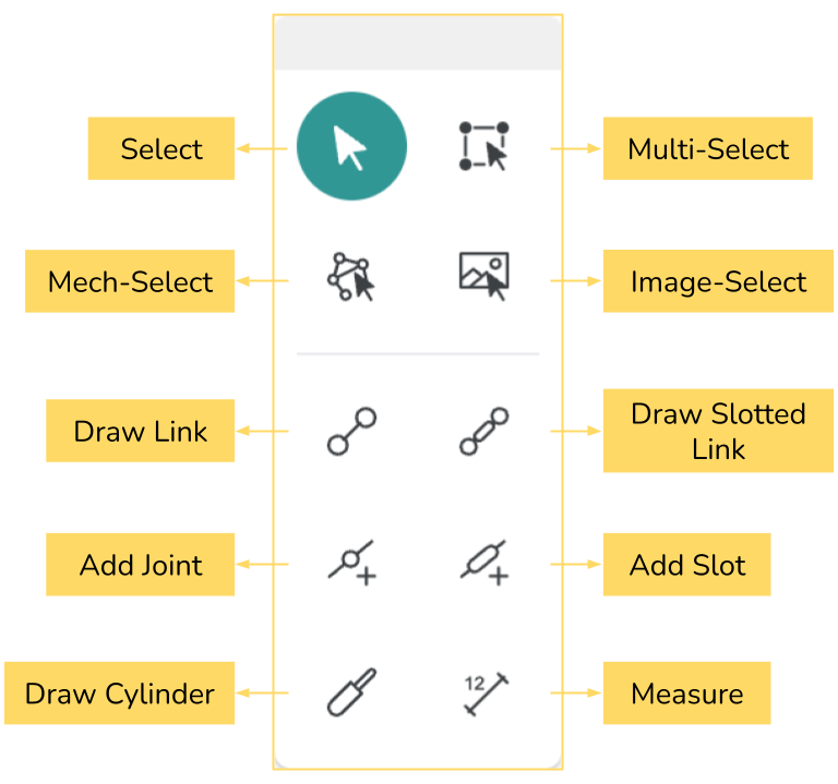
The Base Panel
Draw a Rotating Link
Select Draw Link, and click and drag on the canvas. Each link has two joints at its ends. While a joint is selected, ground it from the context menu, and add a rotary actuator to that same joint.
When a joint is selected, a joint toolbar appears, which allows you to apply different constraints and conditions to it. Most of the icons in this context menu are toggle type.
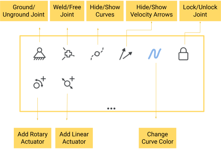
The Joint Toolbar
Make a Three-Bar Structure
Now, let us draw three links connected end to end with each other. This is a structure, which does not permit relative motion of links.
Draw a Four-Bar Mechanism
Now, let us draw four links connected end to end with each other. Ground one link and add a rotary actuator at one of the connected joints of the grounded link. This is called a Four-bar mechanism, which has one Degree of Freedom (DOF). Simply put, each DOF requires one motor to uniquely move a mechanism.
A Crank-Rocker Four-Bar Mechanism
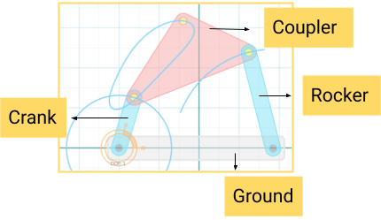
A crank refers to a link that fully rotates, while a rocker oscillates back and forth. A coupler couples crank and the rocker.
Effect of Changing ground link
Experiment with changing the ground link (you have four choices) and see what different motions emerge.
The rectangular link is the grounded one.
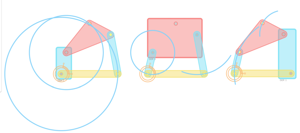
Different Coupler Curves
Add new points on the coupler by selecting the Add Joint option and then clicking on the coupler to see new motion curves. The following image shows a few curves generated by using the Add Joint option from the Base Panel.
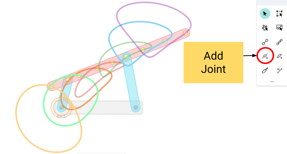
These curves are created by the movement of different points on the coupler.