Panels
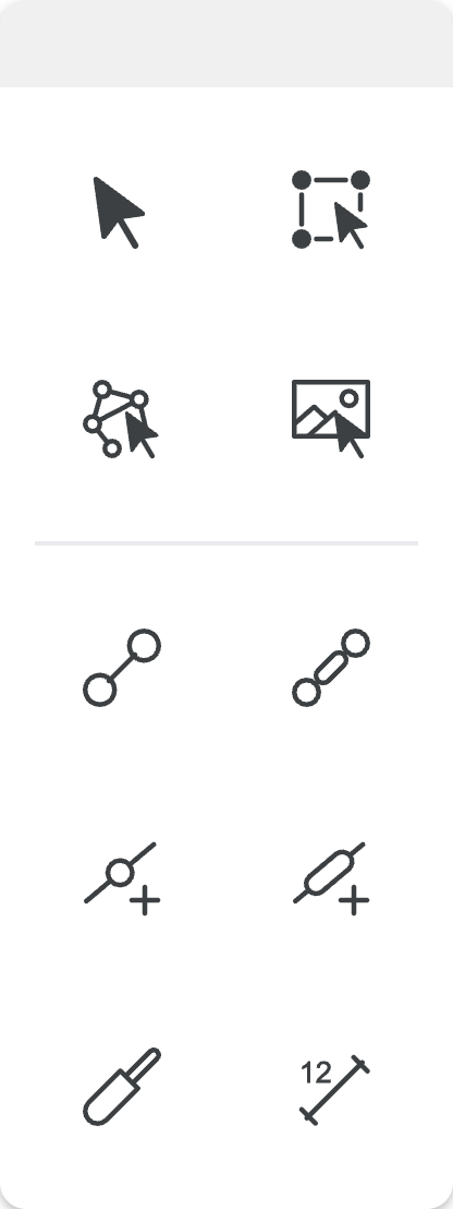
Base Panel
| Icon | Name | Description |
|---|---|---|
 | Select | Choose an object (joint/link) to modify/delete/move. You can click on an empty spot in the canvas to enter "select mode". |
 | Multi-Select | Allows you to create a rectangular selection that contains all the objects you want to select to modify/delete/move. Objects to be selected do not have to be completely inside the drawn selection. A mere crossing of the rectangular selection with the object will select them as well. |
 | Mech-Select | In this mode, the geometry of the mechanism is not changed and the mechanism can be moved by clicking, dragging a joint or link. |
 | Image-Select | Allows you to select an image you have opened in the canvas to resize/rotate/delete/move it. You can also change the opacity of the image. |
 | Draw Link | Lets you draw a link with a revolute joint on each end by clicking and dragging to get the desired link length and position. |
 | Draw Slotted Link | Follow the process of drawing a link, but this link will have a slot inside its body. |
 | Add Joint | Lets you add a revolute joint to a link by clicking anywhere on the link body and dragging either on the link body or outside of it to extend the link body. |
 | Add Slot | Lets you add a slot to a link by clicking on the link body to add a slot between two revolute joints that are closest to where you clicked. |
 | Draw Cylinder | Lets you draw a cylinder with the function of a link that can collapse and expand throughout a motion. Follow the same steps as drawing a link. |
 | Measure | Allows you to measure the length between two joints by clicking on the first joint and then the second joint. Clicking on the dimension shown allows you to edit them as well. |
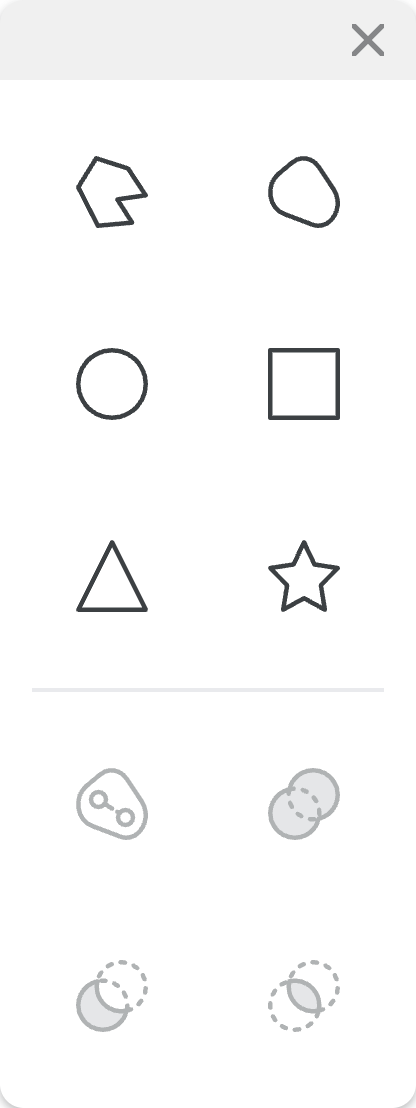
Shapes Panel
| Icon | Name | Description |
|---|---|---|
 | Draw Arbitrary Polygon | Draw a custom polygon by choosing the position and number of vertices for the shape. |
 | Draw Arbitrary Shape | Draw a custom shape by doodling whichever shape you want. |
 | Draw Circle | Draw a circle by clicking to locate the center point and dragging outwards for size. |
 | Draw Rectangle | Draw a rectangle by clicking and dragging a rectangular region. |
 | Draw Triangle | Draw a triangle by drawing a rectangle but only a triangle shaded region is made. |
 | Draw Star | Draw a star by clicking and dragging outwards for size. |
 | Merge | Merges the selected shape with a link drawn inside the shape to create a link. Use the Multi-Select option to select a shape and link to merge them. This option creates a bonafide link with arbitrary shape. |
 | Union | Unites the selected shapes to create a new resulting shape. |
 | Difference | Subtracts one shape from another. The order of subtraction is determined by the shape number. Thus, the new shape is obtained by performing S_i - S_i+1. You can change the overlap to change the order of the shapes. |
 | Intersection | Crates a new shape, which is common to two shapes. |
Note: Merge, Union, Difference, and Intersection can be performed only on a pair of shapes at a time. However, you can repeat the process.
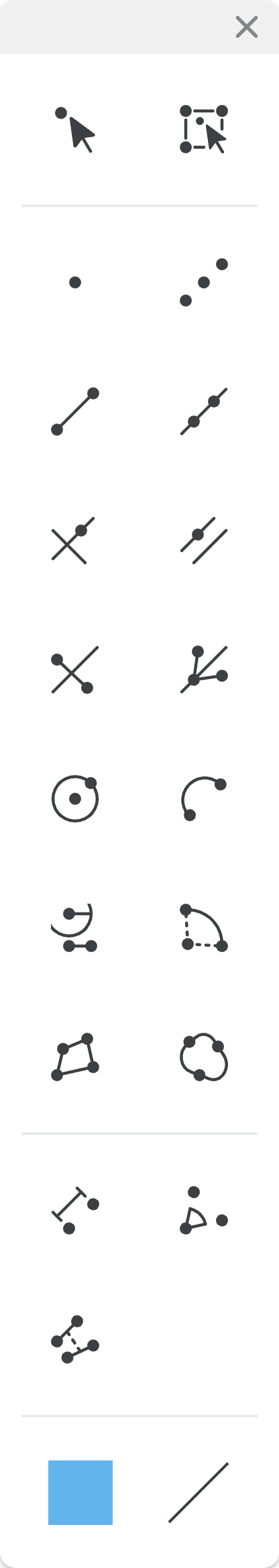
Geomerty Panel
| Icon | Name | Description |
|---|---|---|
 | Geo-Select | The Select mode specify designed for interacting with geometry objects. |
 | Geo-Multi-Select | The Multi-Select mode specify designed for interacting with geometry objects. |
 | Point | Creates a geometry point by clicking on the canvas. |
 | Midpoint | Creates a geometry midpoint by selecting two distinct geometry points. |
 | Segment | Creates a geometry segment by selecting two distinct geometry points. If you click in an area where no point exists, a geometry point is created at that location and automatically selected. |
 | Line | Creates a geometry line by selecting two distinct geometry points. If you click in an area where no point exists, a geometry point is created at that location and automatically selected. |
 | Perpendicular Line | Creates a geometry perpendicular line by first selecting a geometry line object (line, segment, or bisector), then selecting a geometry point. If you click in an area where no point exists, a geometry point is created at that location and automatically selected. |
 | Parallel Line | Creates a geometry parallel line by first selecting a geometry line object (line, segment, or bisector), then selecting a geometry point. If you click in an area where no point exists, a geometry point is created at that location and automatically selected. |
 | Perpendicular Bisector | Creates a geometry perpendicular bisector by selecting a geometry segment object. |
 | Angle Bisector | Creates a geometry angle bisector by selecting three distinct geometry points. |
 | Circle | Creates a geometry circle by selecting two distinct geometry points. If you click in an area where no point exists, a geometry point is created at that location and automatically selected. |
 | Semi-Circle | Creates a geometry semi-circle by selecting two distinct geometry points. If you click in an area where no point exists, a geometry point is created at that location and automatically selected. |
 | Compass | Creates a geometry compass by selecting three distinct geometry points, where the first two points define the compass radius and the third point is the compass center, or by selecting a geometry segment and a geometry point, where the segment defines the radius. If you click in an area where no point exists, a geometry point is created at that location and automatically selected. |
 | Arc | Creates a geometry arc by selecting three distinct geometry points. If you click in an area where no point exists, a geometry point is created at that location and automatically selected. |
 | Polygon | Creates a geometry polygon by selecting any number of distinct geometry points. Selects the first point again to close the polygon. If you click in an area where no point exists, a geometry point is created at that location and automatically selected. |
 | Spline | Creates a geometry spline by clicking and holding on the canvas, dragging to define the spline, and releasing the mouse button. |
 | Distance | Creates a geometry distance by selecting two distinct geometry points. |
 | Angle | Creates a geometry angle by selecting three distinct geometry points. |
 | Sync Segments (beta) | Creates a sync linking by selecting two distinct geometry segment. It syncs only there length. |
 | Color | Allows you to choose the color used when creating geometry objects. |
 | Stroke Style | Allows you to choose the stroke style used when creating geometry objects. |
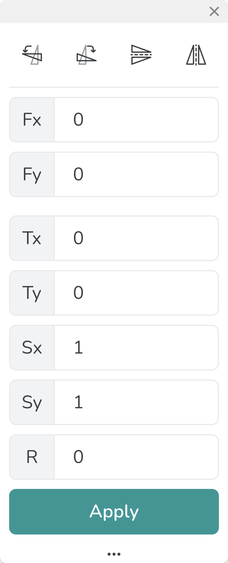
Transform Panel
| Icon | Name | Description |
|---|---|---|
 | Rotate 90 Degrees CCW | Rotates the selected object(s) by 90 degrees in the counterclockwise direction about its designated geometric center. |
 | Rotate 90 Degrees CW | Rotates the selected object(s) by 90 degrees in the clockwise direction about its designated geometric center. |
 | Vertical Mirror | Mirrors the selected object(s) across a horizontal line passing through its geometric center. |
 | Horizontal Mirror | Mirrors the selected object(s) across a vertical line passing through its geometric center. |
Transforming With Values: The rest of the transform panel is unlocked by pressing the extras button. It lets you perform the same actions as the icons but with specific values or coordinates.
- Fx and Fy locate the local reference frame about which the transformations discussed next are performed.
- Tx and Ty are the specific values for translation in each direction about the local reference frame.
- Sx and Sy are the specific values for the scaling about the local reference frame.
- R is the specific amount of degrees you wish to rotate counterclockwise from the positive x-axis about the local reference frame.
Path Synthesis Panel
| Icon | Name | Description |
|---|---|---|
 | Draw Path | Lets you draw a path for the motion by clicking and dragging your cursor. The line will be blue. |
 | Draw Obstacle | Lets you draw an obstacle for the mechanism by clicking and dragging your cursor. The line will be gray. |
 | Emphasize | Emphasizes the part of the motion MotionGen should focus on generating a mechanism for by clicking and dragging the cursor. |
 | De-emphasize | De-emphasizes the part of the motion you have emphasized by clicking and dragging the cursor. |
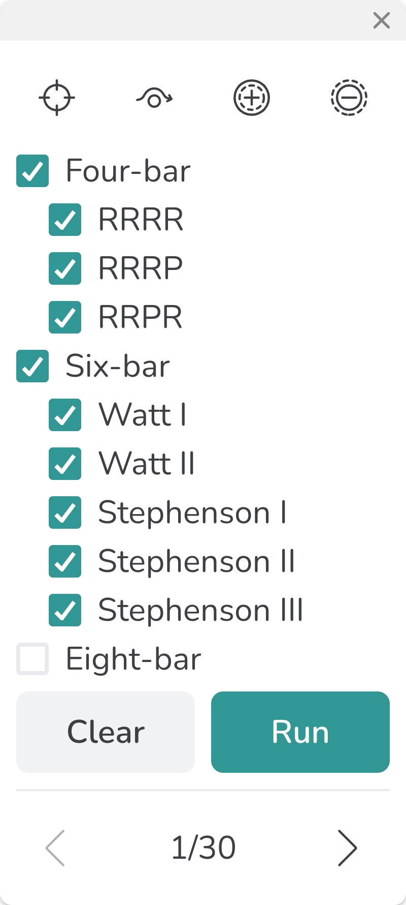
The checkboxes Four-bar, Six-bar and Eight-bar on the panel allow you to select the types of mechanism outputs for a synthesis run.
Motion Synthesis Panel
| Icon | Name | Description |
|---|---|---|
 | Draw Pose | Lets you draw a pose for the mechanism coupler to pass through by clicking and dragging to rotate the pose to the desired orientation. |
 | Draw Point Constraint | Lets you draw a point constraint by simply clicking on the position where you want the joint to be. |
 | Draw Line Constraint | Lets you draw a line constraint by clicking and dragging to determine the orientation of the line constraint. |
 | Toggle Fixed/Moving Constraint | Lets you toggle a fixed/moving point/line constraint to be of the other type. |
 | 3 Arbitrary Poses | Generates 3 arbitrary poses with 2 fixed point constraints |
 | 4 Arbitrary Poses | Generates 4 arbitrary poses with 1 fixed line constraints |
 | 5 Arbitrary Poses | Generates 5 arbitrary poses. |
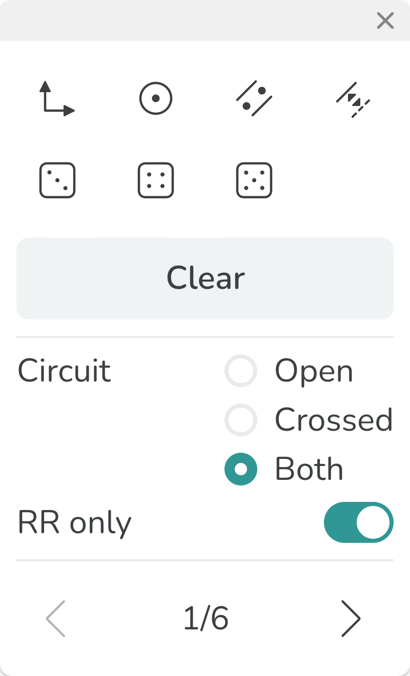
The Motion synthesis returns four-bar mechnaims only. Each four-bar mechanism has two circuit - open and crossed. Use the Circuit ratio button to choose which circuit to display. In some cases, the solutions can be converted to RP or PR joints using a slotted link. Use the RR Only switch to control this behavior.
Rotary Actuator Panel
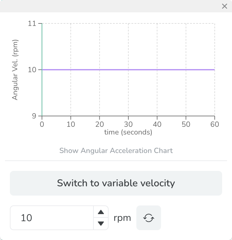
Constant Velocity
| Icon | Name | Description |
|---|---|---|
 | Reverse | Lets you reverse the direction of a constant velocity actuator. For exampe, 10 rpm to -10 rpm. |
Variable Velocity
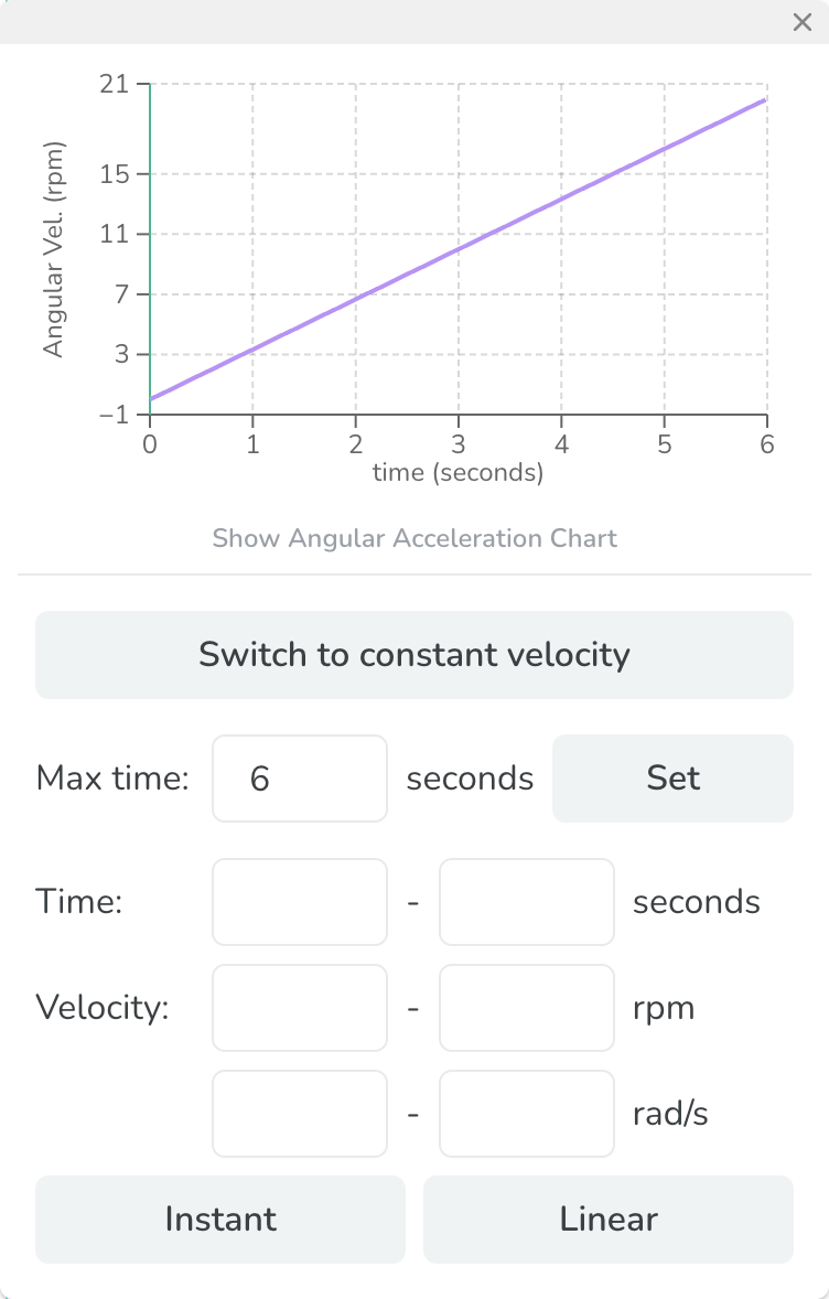
Max time: Defines the maximum time for the simulation. It changes the x-axis on the graph. Use Set button to confirm the input.
Time: Enters the time slot to modfiy.
Velocity: Enters the corresponding velocity between the time slot entered.
After inputs above values, use Instant or Linear button to apply the change to the actuator velocity profile.
Linear Actuator Panel
Constant Velocity
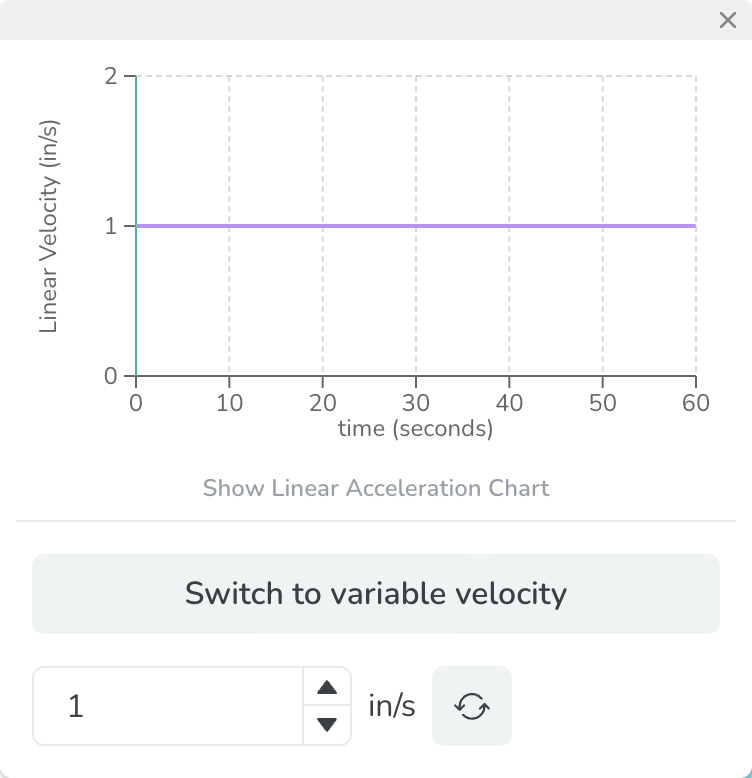
| Icon | Name | Description |
|---|---|---|
| Reverse | Lets you reverse the direction of a constant velocity actuator. For exampe, 1 in/s to -1 in/s. |
Variable Velocity
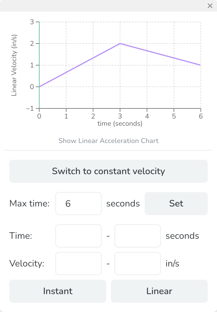
Max time: Defines the maximum time for the simulation. It changes the x-axis on the graph. Use Set button to confirm the input.
Time: Enters the time slot to modfiy.
Velocity: Enters the corresponding velocity between the time slot entered.
After inputs above values, use Instant or Linear button to apply the change to the actuator velocity profile.
Joint Graph Panel
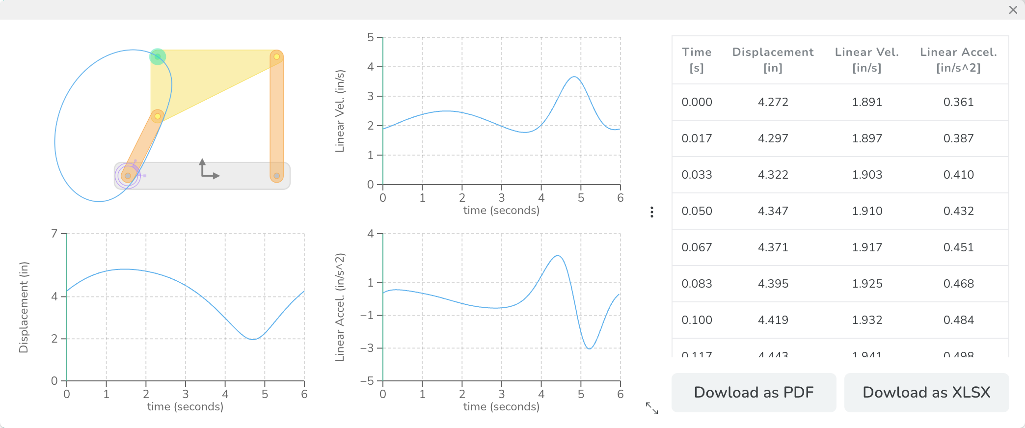
The Joint Graph panel provides Displacement, Linear Velocity, and Linear Acceleration graphs of the selected joint. It displays data in linear units since it is representing a point. The mechanism will also be shown in the panel with the selected joint highlighted. The hidden extras show a table of all the data which can be downloaded as either a pdf or an excel file.
Note: The Displacement is the distance between the selected joint and the frame shown on the mechanism snapshot.
Link Graph Panel
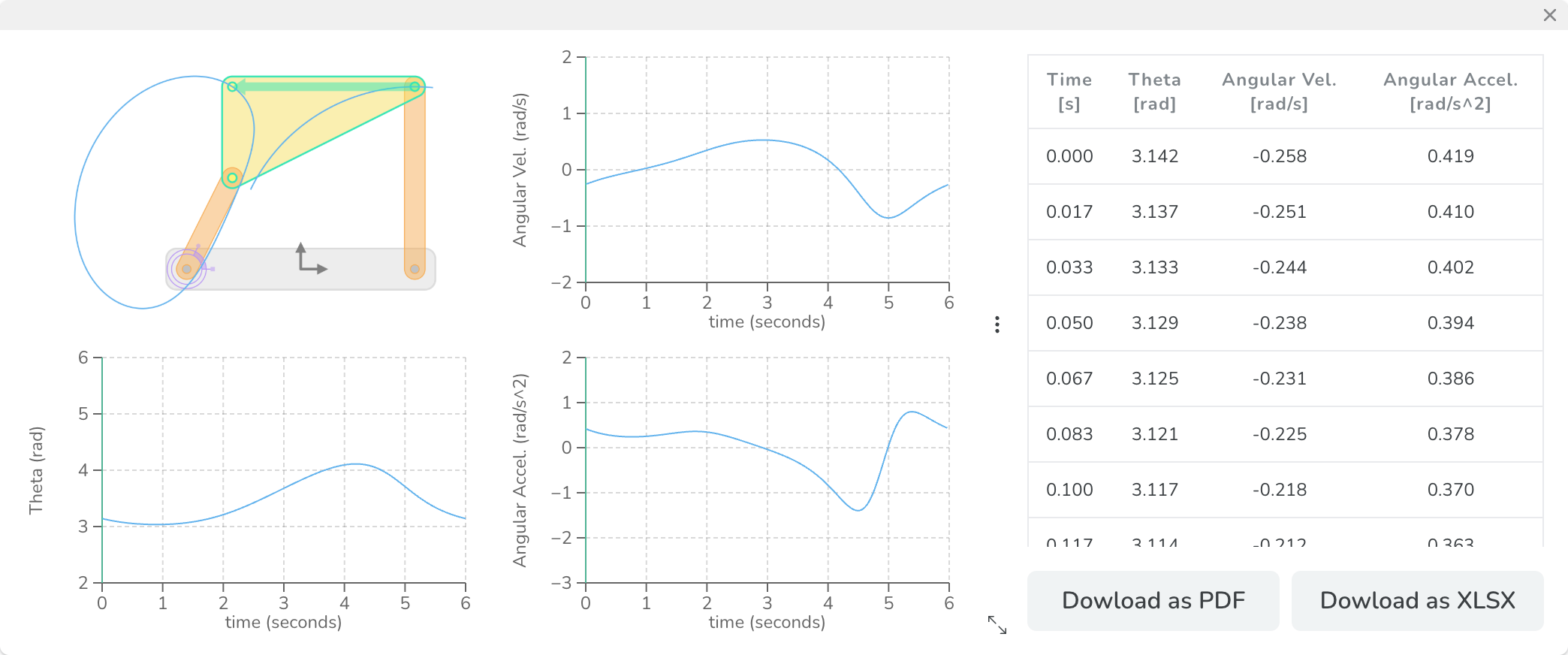
The Link Graph panel provides Theta, Angular Velocity, and Angular Acceleration graphs of the selected link. It displays data in angular units since it is representing a body. The mechanism will also be shown in the panel with the selected link highlighted. The hidden extras show a table of all the data which can be downloaded as either a pdf or an excel file.
Recorder Panel

| Icon | Name | Description |
|---|---|---|
 | Start Recording | Lets you record current tab. |
 | Stop Recording | Lets you stop the recording and immediately have the software start a download of the recording onto your device. |